Design Instructions
- CPU module demands 3.3V power only.
Please provide sufficient power supply to CPU module. Its normal power consumption is about 3.3V/0.25A. Please provide current supply about 3V3/0.8A to CPU module.
- Backup battery provides clock power (1.8V)
This is RTC power supply, and can be connected to battery-power directly. Recommended circuit is shown in Figure 4-2:
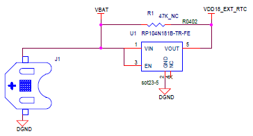
Figure 4-2
- VDD_ADC demands a reference voltage (3V-3.6V)
This is ADC reference voltage(1.8V). Inside the CPU module, it has been connected to 1V8 reference voltage, and there is no need for customer to connect it to an external power source.
- PWR_EN is the CPU module power input enable signal, and 3.3V is active. Recommended circuit is shown in Figure 4-3:
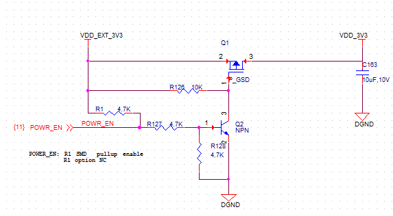
Figure 4-3
- There are two booting modes when using the CPU module.
- The boot mode is using MMC signal when is it high voltage;
- The boot mode is using the NAND signal when it is low voltage.
We suggest user to use pull-up or pull-down resistor when selecting booting mode. Please refer to below diagram:
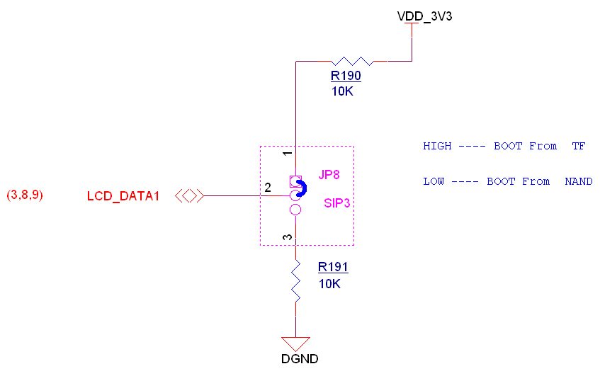
Figure 4-4
- J1 and CN3 are reserved for customers to connect to other signals. Currently we do not use these two interfaces on our designed base board.
- J1 is debug interface
- CN3 is mainly for MMC external interface
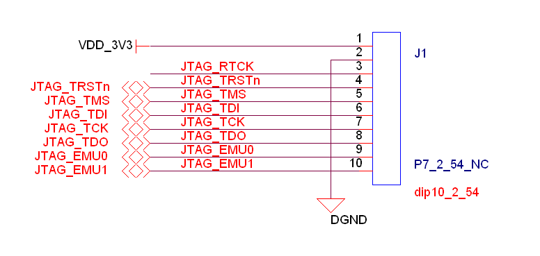
Figure 4-5
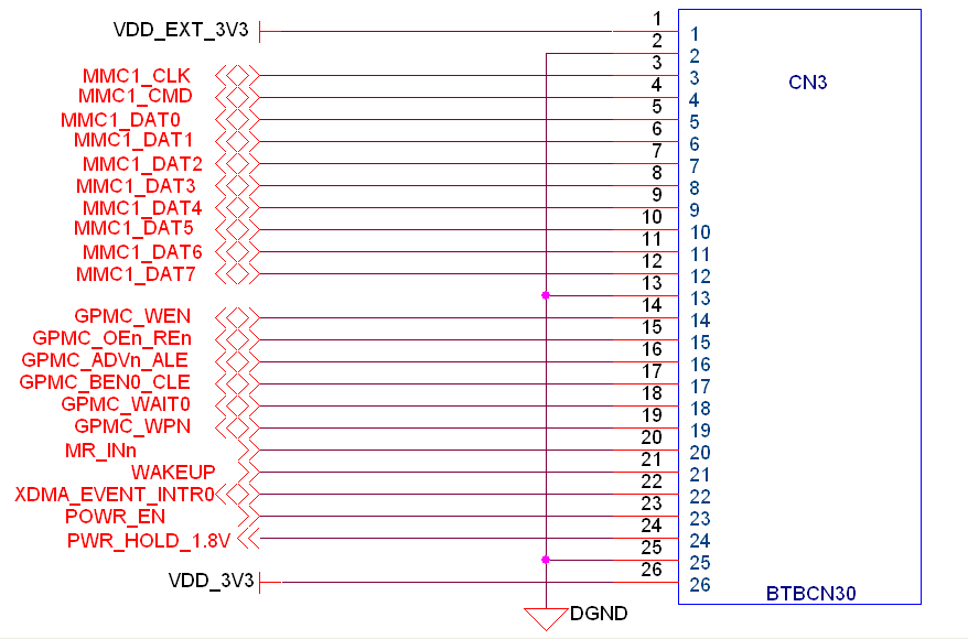
Figure 4-6