Function Module Description
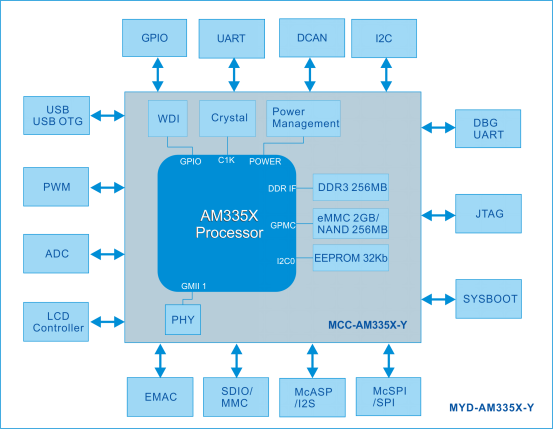
Figure 3-2
Ethernet
MYD-AM335X-Y integrates two Ethernet interface. As shown in Figure 3-2, Ethernet interface 1 or Ethernet interface 2 are GMII interface, translate into physical layer signal by two PHY chips, and then output Gigabit signals by connecting to the integrated block RJ45. Two PHY chips, one is integrated in the MYD-AM335X-Y core board, another is located on the MYB-AM335X-Y floor.
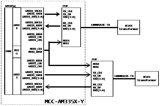
Figure 3-3
SDIO Wi-Fi network card
MYD-AM335X-Y integrates Wi-Fi network card with SDIO interface, connecting the MMC2 interface of AM335X.
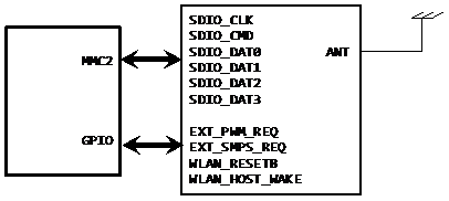
Figure 3-4
LCD Touch Screen
MYD-AM335X-Y integrates 16 bit RGB LCD interface, supporting 480x272 resolution (4.3 inch screen) default, 800 x480 resolution (7 inch screen). You can choose MY-TFT043 or MY-TFT070-K module, MY-TFT043 is 4.3 inch LCD touch screen, and MY-TFT070-K is 7 inch.
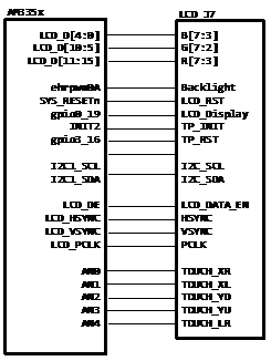
Figure 3-5
Audio CODEC
MYD-AM335X-Y uses audio coding chip SGTL5000, I2S for data communications, I2C0 configuration interface, connected to AM335X McASP0 port, develop two 3.5mm Headset Jack J8 and J9, audio input and output.
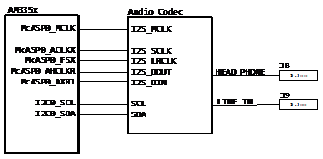
Figure 3-6
Extended Interface
MYD-AM335X-Y led main interface to expansion interface. The main CON2, J13, J14, and a JTAG can also be used for other functions.
- CON2
| 1 | 2 | 3 | 4 | 5 | 6 |
|---|---|---|---|---|---|
| CANH | CANL | GND_ISO | RS485_B | RS485_A | GND_ISO |
图3-7
- J13
| I2C0_SCL | 20 | 19 | I2C0_SDA |
|---|---|---|---|
| NC | 18 | 17 | NC |
| NC | 16 | 15 | NC |
| NC | 14 | 13 | NC |
| NC | 12 | 11 | NC |
| NC | 10 | 9 | NC |
| DCAN0_TX | 8 | 7 | DCAN0_RX |
| UART1_RX | 6 | 5 | UART1_TX |
| NC | 4 | 3 | NC |
| 3.3V | 2 | 1 | 5V |
Figure 3-9
- J14
| I2C1_SCL | 20 | 19 | I2C1_SDA |
|---|---|---|---|
| NC | 18 | 17 | NC |
| NC | 16 | 15 | NC |
| NC | 14 | 13 | NC |
| NC | 12 | 11 | AIN7 |
| AIN6 | 10 | 9 | AIN5 |
| NC | 8 | 7 | NC |
| NC | 6 | 5 | NC |
| NC | 4 | 3 | NC |
| 5V | 2 | 1 | 3.3V |
Figure 3-8