Linux Application
Touch Screen Calibration
Following these steps to calibrate the touch screen:
Open HyperTerminal (baud rate: 115200 Data bits: 8, Parity: None Stop bits: 1, data flow control: none)
There have a default calibration configure for 4.3 inch and 7.0 inch screen in file system that provided on DVD, can also run “ts_calibrate” by manipulating to reconfigure, click the five corresponding calibration points on the LCD screen; HyperTerminal will print the following information:
    xres = 480, yres = 272
    Took 6 samples...
    Top left : X =  563 Y =  880
    Took 6 samples...
    Top right : X = 3555 Y =  920
    Took 6 samples...
    Bot right : X = 3566 Y = 3133
    Took 9 samples...
    Bot left : X =  568 Y = 3058
    Took 2 samples...
    Center : X = 2020 Y = 1903
    -19.553650 0.126868 -0.000548
    -15.654297 -0.001530 0.078228
    Calibration constants: -1281468 8314 -35 -1025920 -100 5126 65536
Backlight Test
Backlight brightness setting range is 1 to100; 1 means the highest brightness and 100 means turning off the backlight brightness. After entering the system, enter the following command in the terminal to test.
- View backlight brightness defaults.
    # cat /sys/class/backlight/pwm-backlight/brightness
    50
- Set the backlight brightness value to 0.
    # echo 100 > /sys/class/backlight/pwm-backlight/brightness
    # cat /sys/class/backlight/pwm-backlight/brightness
    0
Now the backlight is turned off and the screen goes black.
- Set the backlight brightness value to 100.
    # echo 1 > /sys/class/backlight/pwm-backlight/brightness
    # cat /sys/class/backlight/pwm-backlight/brightness
    100
Now the backlight is set to the maximum.
Key Test
User can execute the following command to test K2 and K3 Keys on the development board. Corresponding information will be printed when a key is pressed (Note : If no serial terminal output information when event0 is pressed, can try event1 or event2 be replaced )
    # evtest /dev/input/event0
    Input driver verevdev: (EVIOCGBIT): Suspicious buffer size 511, limiting output to  64 bytes. See http://userweb.kernel.org/~dtor/eviocgbit-bug.html
    sion is 1.0.1
    Input device ID: bus 0x19 vendor 0x1 product 0x1 version 0x100
    Input device name: "gpio-keys"
    Supported events:
      Event type 0 (Sync)
      Event type 1 (Key)
        Event code 1 (Esc)
        Event code 102 (Home)
    Testing ... (interrupt to exit)
    Event: time 1233046739.924451, type 1 (Key), code 1 (Esc), value 1
    Event: time 1233046739.924457, -------------- Report Sync ------------
    Event: time 1233046740.171292, type 1 (Key), code 1 (Esc), value 0
    Event: time 1233046740.171297, -------------- Report Sync ------------
    Event: time 1233046744.075984, type 1 (Key), code 1 (Esc), value 1
    Event: time 1233046744.075989, -------------- Report Sync ------------
    Event: time 1233046744.296675, type 1 (Key), code 1 (Esc), value 0
    Event: time 1233046744.296677, -------------- Report Sync ------------
    Event: time 1233046747.364793, type 1 (Key), code 102 (Home), value 1
    Event: time 1233046747.364798, -------------- Report Sync ------------
    Event: time 1233046747.581543, type 1 (Key), code 102 (Home), value 0
    Event: time 1233046747.581546, -------------- Report Sync ------------
USB HOST Test
- Insert USB flash disk into USB host port (J3 or J4). The system will mount USB flash disk file system under directory “/media” automatically:
    # usb 2-1.4: new high speed USB device number 4 using musb-hdrc
    usb 2-1.4: New USB device found, idVendor=0781, idProduct=5406
    usb 2-1.4: New USB device strings: Mfr=1, Product=2, SerialNumber=3
    usb 2-1.4: Product: U3 Cruzer Micro
    usb 2-1.4: Manufacturer: SanDisk
    usb 2-1.4: SerialNumber: 4320221AE8131B7D
    scsi0 : usb-storage 2-1.4:1.0
    scsi 0:0:0:0: Direct-Access     SanDisk  U3 Cruzer Micro  8.02 PQ: 0 ANSI: 0 CCS
    sd 0:0:0:0: [sda] 7913471 512-byte logical blocks: (4.05 GB/3.77 GiB)
    sd 0:0:0:0: [sda] Write Protect is off
    sd 0:0:0:0: [sda] No Caching mode page present
    sd 0:0:0:0: [sda] Assuming drive cache: write through
    sd 0:0:0:0: [sda] No Caching mode page present
    sd 0:0:0:0: [sda] Assuming drive cache: write through
     sda: sda1
    sd 0:0:0:0: [sda] No Caching mode page present
    sd 0:0:0:0: [sda] Assuming drive cache: write through
    sd 0:0:0:0: [sda] Attached SCSI removable disk
    # cd /media
    # ls
    card       hdd        mmcblk0p1  ram        sda1
    cf         mmc1       net        realroot   union
- Input command to view the contents of USB flash disk:
    # ls sda1/
    u-boot.img         mlo         uImage
    ramdisk.gz         ubi.img
USB DEVICE Test
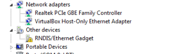
In the USB DEVICE test, connect miniUSB on board to USB on PC to enable ping communication.
- After booting the system of the development board, connect the development board (J2 port) with PC through Mini USB through USB mini B to USB A cable. The USB mini B port is connecting to the development board and USB A port is connecting to PC. The Device Manager will show below devices on PC as shown in Fig.1-2. Right click this device and select “Update Driver Software”.
- Select “install from a list or specific location” and then click “Next” as shown in Fig. 1-3:
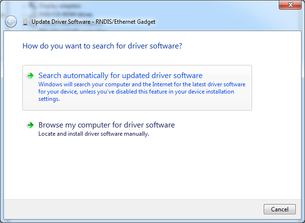
Figure 1-3
- Specify the USB drive path “03-Tools\USBDriver”, then click “Next” and wait for the driver installation as shown in Fig. 1-4:
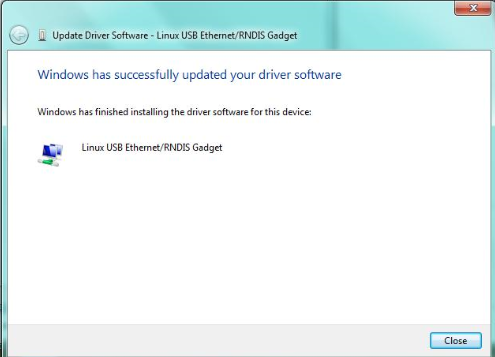
Figure 1-4
- After installation, the USB device as shown in Fig. 1-5 will be displayed in Device Manager:
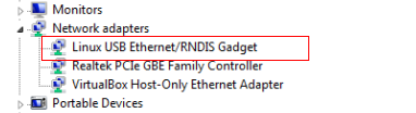
Figure 1-5
After the development board is configured, please click “My Computer->Network Neighborhood->Check Network Connection”; A virtual network adapter will be added at the PC end.
Right-click virtual network adapter at the computer end, left-click “Attribute”, double-left-click to enter the “Internet Protocol (TCP/IP)” to configure the IP address of the virtual network adapter as shown in Fig. 1-6:
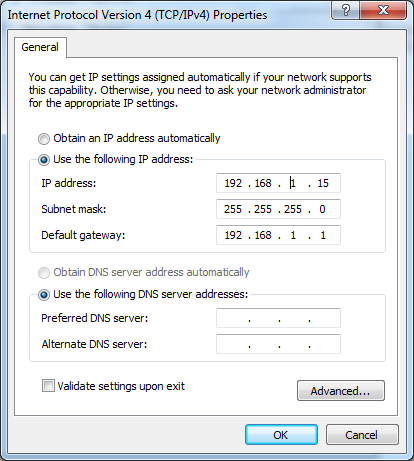
Figure 1-6
- Configure IP and virtual USB network card address of the development board in the same network segment, enter the following commands in the terminal:
    # ifconfig usb0 192.168.1.115
    # ifconfig
    lo        Link encap:Local Loopback
              inet addr:127.0.0.1  Mask:255.0.0.0
              UP LOOPBACK RUNNING  MTU:16436  Metric:1
              RX packets:0 errors:0 dropped:0 overruns:0 frame:0
              TX packets:0 errors:0 dropped:0 overruns:0 carrier:0
              collisions:0 txqueuelen:0
              RX bytes:0 (0.0 B)  TX bytes:0 (0.0 B)
    usb0      Link encap:Ethernet  HWaddr 32:DC:39:3B:E6:84
              inet addr:192.168.1.115  Bcast:192.168.1.255  Mask:255.255.255.0
              UP BROADCAST RUNNING MULTICAST  MTU:1500  Metric:1
              RX packets:2 errors:0 dropped:0 overruns:0 frame:0
              TX packets:0 errors:0 dropped:0 overruns:0 carrier:0
              collisions:0 txqueuelen:1000
              RX bytes:656 (656.0 B)  TX bytes:0 (0.0 B)
- Use ping command to test whether the settings are successful:
    # ping 192.168.1.15
    PING 192.168.1.15 (192.168.1.15): 56 data bytes
    64 bytes from 192.168.1.15: seq=0 ttl=128 time=1.007 ms
    64 bytes from 192.168.1.15: seq=1 ttl=128 time=0.434 ms
    64 bytes from 192.168.1.15: seq=2 ttl=128 time=0.500 ms
- Occurrence of above serial port information indicates that the
testing is successful.
Note: IP address of the network adapter configured in OTG cannot be the same as that of Ethernet interface.
TF Card Test
- Insert a TF card before power on the board, then start the system. The system will mount the file system of the TF card under directory “/media” automatically:
    # cd /media/
    # ls
    card       hdd        mmcblk0p1  ram        union
    cf         mmc1       net        realroot
- Enter the command to view TF card contents:
    # ls mmcblk0p1/
    u-boot.img         mlo         uImage
    ramdisk.gz         ubi.img
Audio Test
MYD-AM335X development board has audio input and output interface. And we have “alsa-utils” audio test tools in the file system, and then users can enter the following commands for testing:
- Recording Test:
Plug in a microphone to test recording:
    # arecord -t wav -c 1 -r 44100 -f S16_LE -v record
    Recording WAVE 'record' : Signed 16 bit Little Endian, Rate 44100 Hz, Mono
    Plug PCM: Route conversion PCM (sformat=S16_LE)
      Transformation table:
        0 <- 0*0.5 + 1*0.5
    Its setup is:
      stream       : CAPTURE
      access       : RW_INTERLEAVED
      format       : S16_LE
      subformat    : STD
      channels     : 1
      rate         : 44100
      exact rate   : 44100 (44100/1)
      msbits       : 16
      buffer_size  : 32768
      period_size  : 2048
      period_time  : 46439
      tstamp_mode  : NONE
      period_step  : 1
      avail_min    : 2048
      period_event : 0
      start_threshold  : 1
      stop_threshold   : 32768
      silence_threshold: 0
      silence_size : 0
      boundary     : 1073741824
    Slave: Hardware PCM card 0 'AM335X EVM' device 0 subdevice 0
    Its setup is:
      stream       : CAPTURE
      access       : MMAP_INTERLEAVED
      format       : S16_LE
      subformat    : STD
      channels     : 2
      rate         : 44100
      exact rate   : 44100 (44100/1)
      msbits       : 16
      buffer_size  : 32768
      period_size  : 2048
      period_time  : 46439
      tstamp_mode  : NONE
      period_step  : 1
      avail_min    : 2048
      period_event : 0
      start_threshold  : 1
      stop_threshold   : 32768
      silence_threshold: 0
      silence_size : 0
      boundary     : 1073741824
- Playback Testing:
Plug in the headphones to hear what have just recorded:
    # aplay -t wav -c 2 -r 44100 -f S16_LE -v record
    Playing WAVE 'k' : Signed 16 bit Little Endian, Rate 44100 Hz, Mono
    Plug PCM: Route conversion PCM (sformat=S16_LE)
      Transformation table:
        0 <- 0
        1 <- 0
    Its setup is:
      stream       : PLAYBACK
      access       : RW_INTERLEAVED
      format       : S16_LE
      subformat    : STD
      channels     : 1
      rate         : 44100
      exact rate   : 44100 (44100/1)
      msbits       : 16
      buffer_size  : 32768
      period_size  : 2048
      period_time  : 46439
      tstamp_mode  : NONE
      period_step  : 1
      avail_min    : 2048
      period_event : 0
      start_threshold  : 32768
      stop_threshold   : 32768
      silence_threshold: 0
      silence_size : 0
      boundary     : 1073741824
    Slave: Hardware PCM card 0 'AM335X EVM' device 0 subdevice 0
    Its setup is:
      stream       : PLAYBACK
      access       : MMAP_INTERLEAVED
      format       : S16_LE
      subformat    : STD
      channels     : 2
      rate         : 44100
      exact rate   : 44100 (44100/1)
      msbits       : 16
      buffer_size  : 32768
      period_size  : 2048
      period_time  : 46439
      tstamp_mode  : NONE
      period_step  : 1
      avail_min    : 2048
      period_event : 0
      start_threshold  : 32768
      stop_threshold   : 32768
      silence_threshold: 0
      silence_size : 0
      boundary     : 1073741824
Ethernet Test
Note: ETH0 Ethernet port printing on the board corresponded with eth1 in the system, and ETH1 corresponding with the eth0.
MYD-AM335X has two Ethernet ports eth0 and eth1. Here take testing eth0 as an example to exhibit the testing process. Eth1 can also be tested using the same method, but remember to use the following command to disable eth0:
# ifconfig eht0 down
Connect the development board to PC with a crossover cable, or connect the development board to the switch or router by straight line. Please note that: when use a crossover cable for connection, the PC must have two network cards in case the development board needs to access external network. One network card connects to the development board; another network card connects to external network. The two network cards should be set to bridge mode. The following test is based on a crossover cable connection and dual NIC bridged mode.
In the PC’s “Network Connections” window, select the two network cards to be bridged, right-click and select "bridge" in the context menu to bridge the two network cards (in Windows XP/Windows 7 as an example).
Allocate the development board with an IP address that is not currently occupied by any other device in the LAN. Here use the address: “192.168.1.222” as an example:
# ifconfig eth0 192.168.1.222 up
- Test whether the development board and PC network is successfully connected through ping command. (Here the host IP is 192.168.1.13). Ping the development board:
    $ ping 192.168.1.222
    PING 192.168.1.222 (192.168.1.222) 56(84) bytes of data.
    64 bytes from 192.168.1.222: icmp_req=1 ttl=64 time=0.432 ms
    64 bytes from 192.168.1.222: icmp_req=2 ttl=64 time=0.220 ms
    64 bytes from 192.168.1.222: icmp_req=3 ttl=64 time=0.246 ms
    64 bytes from 192.168.1.222: icmp_req=4 ttl=64 time=0.210 ms
    64 bytes from 192.168.1.222: icmp_req=5 ttl=64 time=0.241 ms
    --- 192.168.1.222 ping statistics ---
    5 packets transmitted, 5 received, 0% packet loss, time 3998ms
    rtt min/avg/max/mdev = 0.210/0.269/0.432/0.084 ms
Ping PC:
    # ping 192.168.1.13
    PING 192.168.1.13 (192.168.1.13): 56 data bytes
    64 bytes from 192.168.1.13: seq=0 ttl=64 time=2.298 ms
    64 bytes from 192.168.1.13: seq=1 ttl=64 time=0.401 ms
    64 bytes from 192.168.1.13: seq=2 ttl=64 time=0.412 ms
    64 bytes from 192.168.1.13: seq=3 ttl=64 time=0.356 ms
    --- 192.168.1.13 ping statistics ---
    4 packets transmitted, 4 packets received, 0% packet loss
    round-trip min/avg/max = 0.356/0.866/2.298 ms
CAN Test
MYD-AM335X development board has one CAN port, communication baud rate up to 1M It can be tested through the following steps. (here use two MYD-AM335X development board for testing)
Connect U16’s the 7th feet (CANL) and the 8th feet (CANH) of the two boards, respectively.
Set the baud rates of two boards’ can0 communication to 50KBps respectively, and enable can0 devices:
    # canconfig can0 bitrate 50000 ctrlmode triple-sampling on
    # canconfig can0 start
- Execute the following command in one development board to set can0 on the receiving state:
# candump can0
Execute the command; the terminal will print the received data.
- Execute the following command to send packets:
Note:
* This command sends data one time on excution; Resending requires to re-enter the command.

* Please ensure that the other side of communication is on the receiving state. And only thus will the receiver side print the sent information.
# cansend can0 123#1122334455667788
After executing this command, examine the receiving end to make certain whether or not the data is received successfully.
- Turn off the device:
# canconfig can0 stop
RS485 Test
MYD-AM335X development board has one RS485 port. communication baud rate up to 115200 It can be tested through the following steps. (Here use two MYD-AM335X development board for testing)
Connect U16’s the 4th feet(RS485A) and the 5th feet(RS485B) respectively.
Copy the testing procedure “rs485test” under the CD’s directory “05-Linux Source\Examples\RS485_Test” to a TF card. Then, copy the file from the TF card to the two development boards, respectively:
    # cp  /media/mmcblk0p1/rs485_test  ./
    # chmod  +x  rs485_test
- Execute the following command in the two development boards, respectively, Occurrence of following serial port information indicates that the RS485 testing is successful.
    # ./rs485_test -d /dev/ttyO1 -b 9600
    /dev/ttyO1 SEND: 1234567890
    /dev/ttyO1 RECV 10 total
    /dev/ttyO1 RECV: 1234567890
    /dev/ttyO1 SEND: 1234567890
    /dev/ttyO1 RECV 10 total
    /dev/ttyO1 RECV: 1234567890
    /dev/ttyO1 SEND: 1234567890
    /dev/ttyO1 RECV 10 total
    /dev/ttyO1 SEND: 1234567890
RTC Test
The development board contains hardware clock for saving and synchronizing the system time. Test can be made with the following steps.
- Set the system time as “January 10, 2014 2:17 pm”:
    # date 011014172014
    Fri Jan 10 14:17:00 UTC 2014
- Write the system clock into RTC:
# hwclock -w
- Read the RTC:
    # hwclock
    Fri Jan 10 14:17:22 2014  0.000000 seconds
Now the RTC clock has been set as “January 10, 2014”; the system clock is saved in the hardware.
- Restart the system, enter the following commands to renew the system
    # hwclock -s
    # date
    Fri Jan 10 14:19:55 UTC 2014
There can be seen that the system time is set as hardware time.
Note: RTC will halt up after power down for it is the CPU’s bug; TI has released a corrigendum, please refer to it for specific information.
Serial Test
Short circuiting UART2’s (J13) RX_3V3 pin and TX_3V3 pin, copy the file “rs232_test” under directory “05-Linux_Source\Examples\RS232_Test” from the CD to the TF card, insert the TF card to the MYD-AM335X TF slot, and input the commands as below:
    # cp  /media/mmcblk0p1/rs232_test  ./
    # chmod  +x  rs232_test
    # ./rs232_test -d /dev/ttyO2 -b 115200
Printing the following information means the test is successful.
    /dev/ttyO2 SEND: 1234567890
    /dev/ttyO2 RECV 10 total
    /dev/ttyO2 RECV: 1234567890
    /dev/ttyO2 SEND: 1234567890
    /dev/ttyO2 RECV 10 total
    /dev/ttyO2 RECV: 1234567890
    /dev/ttyO2 SEND: 1234567890
    /dev/ttyO2 RECV 10 total
    /dev/ttyO2 RECV: 1234567890
    /dev/ttyO2 SEND: 1234567890
    /dev/ttyO2 RECV 10 total
    /dev/ttyO2 RECV: 1234567890
    /dev/ttyO2 SEND: 1234567890
    /dev/ttyO2 RECV 10 total
HDMI Test
The MYD-AM335X has an HDMI (High Definition Multimedia Interface) interface. User can connect their monitor with the development board through HDMI cable and then display high-definition images. Below we will introduce how to use HDMI on MYD-AM335X.
Note: if you are using the compiled u-boot with HDMI configuration file, the HDMI can be used directly and no need to follow below steps. Please refer to 1.4.3 to install U-boot source and compile. You cannot use the HDMI and LCD at the same time.
Please connect the monitor with the development board through HDMI cable;
Boot the development board, press any key to get into u-boot when the u-boot prompts counts;
Input following commands under u-boot command line to set the display mode. The supported modes are hdmi640x480 and hdmi720p. Here we use hdmi720p as an example:
    Hit any key to stop autoboot:  0
    # set optargs 'board-am335xevm.display_mode=hdmi720p'
- Input boot command to start up the system:
# boot
- After the system booted, the image will output from the monitor.
Dual Ethernet Test
Note: ETH0 Ethernet port printing on the board corresponded with eth1 in the system, and ETH1 corresponding with the eth0.
Two net ports on the MYD-AM335X can be used at the same time. The following will describe how to use them.
- The IP of eth0 set to 192.168.1.2, Command as following:
# ifconfig eth0 192.168.1.2
- The IP of eth1 set to 192.168.2.2, Command as following:
# ifconfig eth1 192.168.2.2
- Test the two nets:
Host A and Host B in the Local Network, the IP is 192.168.1.3 and 192.168.2.3 respectively. Enter the following in the board to test eth0.
# ping 192.168.1.3
The follow show eth0 is work well:
    PING 192.168.1.3 (192.168.1.3): 56 data bytes
    64 bytes from 192.168.1.3: seq=0 ttl=128 time=9.689 ms
    64 bytes from 192.168.1.3: seq=1 ttl=128 time=3.865 ms
    64 bytes from 192.168.1.3: seq=2 ttl=128 time=3.807 ms
    64 bytes from 192.168.1.3: seq=3 ttl=128 time=3.730 ms
Enter the following command to test eth1:
# ping 192.168.2.3
Shown below when eth1 is working:
    PING 192.168.2.3 (192.168.2.3): 56 data bytes
    PING 192.168.2.3 (192.168.2.3): 56 data bytes
    64 bytes from 192.168.2.3: seq=0 ttl=64 time=0.453 ms
    64 bytes from 192.168.2.3: seq=1 ttl=64 time=0.208 ms
    64 bytes from 192.168.2.3: seq=2 ttl=64 time=0.147 ms
    64 bytes from 192.168.2.3: seq=3 ttl=64 time=0.132 ms